|


| |
|
What do computer floppy disk drives and printers have
to do with making model aircraft?
Read on to find out. |
|
Having developed the skill set and
techniques for manually cutting foam wings many years ago, primarily
because I have never really liked to build normal built-up wings for
model aircraft. I have cut many different types of wings for myself,
friends and even for a time, developed and manufactured wings for a
model kit manufacturing company. However, cutting foam wings manually
requires the making of templates for the hot wire to move over so that an
accurate wing aerofoil shape can be reproduced.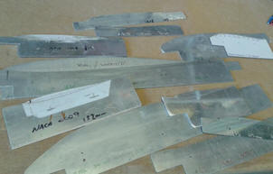 If the wing is of
multiple taper or different sections along the wing then the more
templates you need to complete the process. If the wing is of
multiple taper or different sections along the wing then the more
templates you need to complete the process.
Producing wing section templates is somewhat time consuming and the wing
is only as accurate as the template, so these are key to an accurate
wing. If the templates are for a bespoke model, then they may only be
used once then put away in the cupboard, probably never to see the light
of day again. It seems almost a waste to go to such effort and cost of
materials to just use these once.
Furthermore, when actually using the
templates to cut wings with a hot wire, care has to be taken in
producing highly tapered wings especially if you cut the wings on your
own as the wire moving over the wing tip template has to move at a
different rate (normally slower) than the root template to ensure the
wing is accurate; this of course this takes a little skill to get right.
Often is the case that the outer tip wire movement becomes a little
jerky resulting in ridges forming in the foam surface that needs
attention with a little fine grit sand paper. |
|
Around 10 years ago, having found a few
interesting and informative website, I decided to set myself a challenge
and build a CNC machine that would do the job of cutting foams wings
without the use of templates. The advantage of this is that you simply
hook up the computer to the controller and mechanism, tell it what wing
section you need, the dimensions, what spars your need and introduce the
foam to the CNC cutter and press go………. Well, it sounds simple, but to
see these machines in action leaves you in awe that such intricate
shapes can be produced. So why has it taken me some 10 years to finally
get to finish building the machine?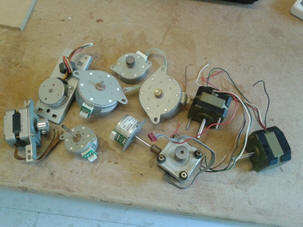 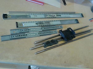
My first problem was finding some examples
of what I should build and there are quite a few website out there that
can provide plans and advice on what to do. Manufacturing your own seems
so much appealing that spending hundreds, or in some cases, thousands of
pounds to buy a commercial foam cutting CNC machine. Having decided on
the way forward, I subsequent bought a CNC controller kit from the
States on the advice of a popular modelling CNC website and from where I
also downloaded a plan for the suggested mechanics. This was the start
of my dilemma.
I
wasn’t sure on the design of the mechanics. I suppose I wanted something
a little more Gucci than what others had done, but I certainly wasn’t
going to shell out the hundreds of pounds to buy a ready-to-go machine.
I couldn’t decide what running gear to use; do I use drawer runners as
per the plan? the items available in the DIY stores and the ones I
acquired or purchased just didn’t give me the necessary fore and aft
movement of a round 500mm without problems. There were also commercial CNC
rails available, but these were very costly; also another non-starter.
My interest started to wane until I spotted someone casting some really
 old unwanted 5¼ computer floppy
disk drives into a skip. Having read that
these would have some stepper motors in them, I approached the guy and
rescued five units that were all the same and subsequently found these
had indeed, a well know Tandon stepper motor in each. old unwanted 5¼ computer floppy
disk drives into a skip. Having read that
these would have some stepper motors in them, I approached the guy and
rescued five units that were all the same and subsequently found these
had indeed, a well know Tandon stepper motor in each.
With
that lucky find, the impetus was well and truly alive again. More
thoughts on carriages and running gear pushed me in the direction of the
rails and carriages in computer printers, which again resulted in me
finding some old printers that were being disposed of. I was on a roll,
what’s more, even the printers has some usable stepper motors in them. -
more choice!
However, this was taking up too much time when all I wanted was to do
was build
and fly models to meet competition deadlines, which meant that the
CNC project was moth balled, I just didn’t feel I had enough time or clear
direction to continue with the project given the problems presented to
me to create exactly what I had in mind. There seemed to be too many
issues to overcome and not enough time in the day to sort them out.
|
|
Well,
it’s now all change! ……………………I’ve not only gone Hi Tech, but achieved
success on a budget too!
Over the years, I would occasionally dust
down the CNC project box and contemplated the bits that I had acquired
and considered progressing the wing cutter, but quickly put the
stuff back on the shelf, again building and flying came first. What’s
more, my manual wing cutting is fine so there was no real need to spend
too much time on the CNC machine. But there have been a few model
projects from my wish list that have not really taken shape until now
because of the amount of work involved to make wing cutting templates
for what might actually be the wrong wing section given the nature of
R&D.
Well, move the clock forward in time some 10 years to the present day, a few
new ideas and I have now assembled my CNC foam cutter representing almost what I had
in mind and the outcome is, I might say so myself, mightily impressive.
|
|
Electronics:
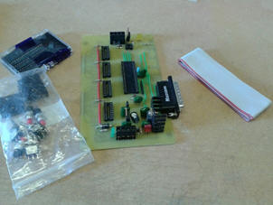
I first built the CNC electronic controller kit that I had purchased
some time ago, but then discovered that as technology has moved on and
the computers I now have, no longer have a parallel output to connect up
the controller… Mmm, A serious rethink was required, so having spoken
about my idea with a few friends at work, it was suggested that I could
purchase a good USB CNC controller that will control 4 axis fairly
cheaply. So for a Yorkshire man with short arms and deep pockets it was
a difficult decision as I wanted to keep the costs of the project to a
minimum. So after some serious trawling of the internet and found that
for the price of a little over half a tank of petrol I could purchase a
new USB controller. Without waiting too long, the order was placed and
a few days later it was like Christmas…… I had a new toy to play with!
What better way than having actually spent some money to motivation me
and get the machine finally sorted.
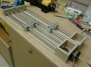
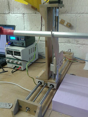
I still had the dilemma of the mechanics for the fore and after
carriages, but I soon found the right rails for my project. 12mm ground
rails and respective carriages, again purchased cheap from ebay. These
have been used for the fore and aft carriages that sit either side of
the block of foam, on to which, I have mounted the vertical rails and
carriages from the old printers, making up the towers.
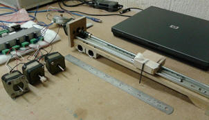
The idea of the machine is to have 4 axis that can move independent of
each other, providing a fore and aft and vertical movement.
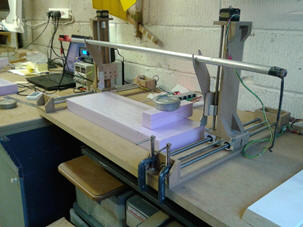
The Mechanism:
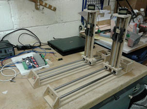  The
mechanism base and framework was produced from 9mm MDF cut to shape and
drilled prior to assembly. The carriages run on the respective rails
driven by a 6mm lead screw attached to the Stepper motor and which
passes through a 6mm nut fastened to the carriage. The towers, again
made from 9mm mdf utilising the old printer rails and associated
carriages, these have a bronze bush that glides along the rails rather
than full bearing, but work quite well, although they have required a
little more care in the set up to ensure they do not bind and cause the
steppers to miss a timing step due to the lack of torque. Well, these
stepper motors were designed for computer floppy drives not the purpose
that they were now being subjected to. However, I have now managed to
improve them by increasing the working voltage a little and achieving the
optimum set up on the controller. The
mechanism base and framework was produced from 9mm MDF cut to shape and
drilled prior to assembly. The carriages run on the respective rails
driven by a 6mm lead screw attached to the Stepper motor and which
passes through a 6mm nut fastened to the carriage. The towers, again
made from 9mm mdf utilising the old printer rails and associated
carriages, these have a bronze bush that glides along the rails rather
than full bearing, but work quite well, although they have required a
little more care in the set up to ensure they do not bind and cause the
steppers to miss a timing step due to the lack of torque. Well, these
stepper motors were designed for computer floppy drives not the purpose
that they were now being subjected to. However, I have now managed to
improve them by increasing the working voltage a little and achieving the
optimum set up on the controller.
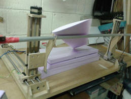
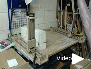 I
initially assembled the machine and connected the Nichrome hot wire
between the two towers which worked well, but it took some setting up to
get the heat of the wire and speed right, but the results were
encouraging. Whilst I am told that the machine will work fine at a metre
distance between towers even for shorter wings, I have decided to follow
the lead from a friend of a friend who uses a commercial unit, to allow for one of the carriages to
be movable to accommodate smaller wing panels and possibly maintain a
better degree of accuracy for the tip of each panel. However, this will
necessitate different lengths of cutting wire and with it, different
heat and speed settings. I
initially assembled the machine and connected the Nichrome hot wire
between the two towers which worked well, but it took some setting up to
get the heat of the wire and speed right, but the results were
encouraging. Whilst I am told that the machine will work fine at a metre
distance between towers even for shorter wings, I have decided to follow
the lead from a friend of a friend who uses a commercial unit, to allow for one of the carriages to
be movable to accommodate smaller wing panels and possibly maintain a
better degree of accuracy for the tip of each panel. However, this will
necessitate different lengths of cutting wire and with it, different
heat and speed settings.
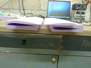
I have subsequently suspended my old wing cutting bow from the vertical
carriages so that no matter how far apart the towers are placed the
speed set up and wire heat voltage and current parameters remain
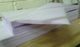
constant. Lots of pieces of cut foam later to work out the correct
settings and get the machine calibrated has resulting in some pleasing
results Including wing sections that has an accurately placed span wise
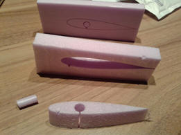
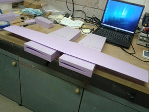
hole for a wing joiner, all cut in just one pass. The example in the
photo is the 100mm root section of NACA wing section aerofoil with a
10mm joiner hole.
I have now got the wherewithal to cut an accurate “Midge” wing from
which I can make a mould, the idea being to make the ultimate hollow
composite wing - Just because I can, and it’s a new challenge; and
that’s just a start.
I have plans for a new 4.2m wing for my 5th scale Janus glider fuselage
which has a multiple sweep forward leading edge to the wing, a multiple
aerofoil 6 panel wing for a 3m performance glider, for which I have had
the fuselage for about 6 years. And who knows what is next.
Timer to go and be creative.
|
|
 |
|
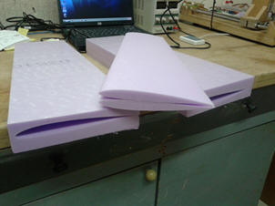
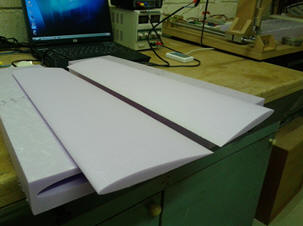
A few weeks on and I have now made some
modifications to the CNC wing cutter.
I have totally remade the MDF framework
and protected these with acrylic varnish. I have turned the towers
through 90 degrees to reduce the lateral movement. I now have bearings
at each end of the lead screws which have also been replaced with
Stainless steel threaded rod. The major change though, has been the
replacement of the old printer rails and carriages on the towers with
8mm ground rails and associated bearing carriages. This was necessary as
the stepper motors were having problems with overcoming the friction
caused by the binding carriages and the weight of the cutting bow. The
result is so much better and actually reduces the minor ridges in the
finished cut foam surface.
Last night I quickly set up the machine by
inputting the standard setup parameters worked out over the last few
weeks of calibration. 20 minutes later a pair of wings for the Midge
model that I am really proud of. Yes, definitely a better finish than by
hand.
So has the effort been worth it?.........
most definitely!
This just proves that a dream can become
reality and not cost the earth to gain exceptional results, it just needs a little
ingenuity, focus and of course, motivation.
Not just a new toy to play with, but
something that will allow me to cut accurate wings with minimum effort.
I don't expect the machine will get a huge amount of use at this time,
but it is now available when needed to progress my future projects. I
just need to buy some more foam!!!! |
 |
|